|
|
|
CHP Logic Relay (1 of 6)
|
| |
|
Quantity in Basket:
None
Catalog No.: CHP-RLY
Price: $47.00
Shipping Weight: 0.10 pounds
Sorry, we are no longer taking orders for the CHP Logic Relay (1 of 6) on our legacy website. Please visit our new website at Corbins.com for all future orders. Any question/concerns you can reach us at sales@corbins.com Thank you
|
| |
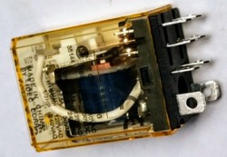
This is a plug-in logic relay, double pole/double throw, which is one of the six relays plugged into the circuit board in the CHP-1 Hydro Press. They are interchangeable and trouble shooting for a bad relay can be done by exchange, and then watching for a change in the press behavior. A wiring diagram is available on www.Corbins.com web site to help determine which relay controls specific press functions.
Relays are held in place by a wire clip, and plug into sockets mounted on the fiberglass printed circuit board. Although relays seldom fail, they are relatively inexpensive and easy to change (with the power plug removed from the outlet!). There are eight pins on the relay. Two are mounted so they face parallel to the long side, and are the coil connections. The other six are mounted in two rows of three each. The pins nearest the edge, opposite from the coil pins, are the normally open side of the contacts. The middle pins are the normally closed contacts, and the common or armature connections are the two pins nearest to the coil pins.
A good relay, unplugged from the board, should show zero ohms (short) between each of the sets of outside pins in the row of three (N.C. connection), and no connection to the middle pin in each row (N.O. connection). The two pins turned at an angle to the other six (coil) should read about 120 ohms on an ohmmeter. Applying 110-120v 60hz to the two coil pins should snap the armature down so that there is a short (zero ohms) between the middle pin and the armature pin (which is closest to the coil pins).
The three most common failure modes for this kind of relay are:
- Burned contacts which stick together.
- Burned contacts which do not make a connection.
- Open coil winding.
In a pinch, burned contacts can be temporarily fixed by carefully removing the clear plastic cover, with the relay removed from the circuit, and using a contact burnishing tool to clean the contacts. A 600-grit abrasive cloth can also be used for cleaning, or a 400-grit cloth for more severe pitting removal. The problem with this repair is that the plating on the contacts has been burned away and the pitting will return more quickly. But it can get a machine up and running for a while, until a replacement relay arrives.
Do not substitute relays unless you are absolutely certain that the contact pin connections are the same, and the coil resistance is the same as the original. Improper substitutions can cause serious damage to the circuit, wiring, destroy the circuit board, etc., before the circuit breakers have time to react.
Relays are normally kept in stock and delivery time should be short enough so that the risk of using the wrong part is not worth taking.
|
|